Example: How to model Diffusion through a Membrane using a Baffle Interface
2023-11-14T16:30:59.000-0500
Summary
To model the diffusion through a membrane a baffle interface is created. Using a data mapper the partial pressure difference between the two sides of the interface drive the species flux through the membrane.
Details
| Attachments: | Membrane.sim (104 MB) |
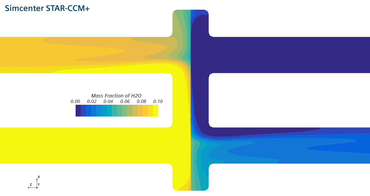
The flow is air with 10% steam incoming from the bottom left and dry, pure air from the top right. In the middle a membrane is dividing the two sides. This article describes how to model the species flux through the membrane.
Modelling Principle
The species transfer through a membrane is defined by the concentration/partial pressure boundary layers on both sides and the diffusion gradient through the membrane itself. In CFD applications you can resolve the boundary layer in the simulation. The diffusion through the membrane could be modelled using a porous region. But this is often neglected because the membrane is relatively thin.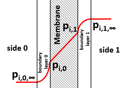
The species flux is modeled using Fick's law
| mi = | Di | • | ∂pi |
| RT | ∂x |
| mi = Φi • ( pi,0 - pi,1 ) , |
Simulation Setup
As seen above the equations are very simple. Unfortunately calculating the partial pressure difference requires some setup. When evaluating on one side of the interface, the value for the partial pressure on the other side is not automatically available.These steps are needed to model this in Simcenter STAR-CCM+:
- Make sure you already have a baffle interface in place of your membrane. You may enable the conducting option to get heat transfer through the membrane.
- Create a parameter to define the "permeance" with the Dimensions Mass/Time/Pressure/Length^2. For this example we choose a permeance of 1e-8 kg/Pa/m2/s.
- Create a field function to define the partial pressure of the relevant components.
- Rename the function to "1_pH2O".
- The Definition is: "$MoleFractionH2O * $AbsoluteTotalPressure".
- Create a Surface Data Mapper.
- Rename it to "MAPP [0-1]".
- Set the source to the baffle interface boundary [0].
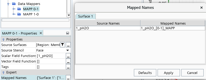
- Click on the "..." under the Mapped Names to change the mapped function name to "1_pH2O_[0-1]_MAPP".
- Set the target to the baffle interface boundary [1].
- Set the source and target stencil to 'Face'.
- Under Update activate the Iteration trigger and automatically update the data mapper every iteration. This does cause some computational expense, but the data mapper is quite efficient and also parallelized.
- Create a copy of the previously created Surface Data Mapper for the other direction. Set the name accordingly to "MAPP [1-0]", also the function name to "1_pH2O_[1-0]_MAPP". Also, switch the source and target parts.
- Create a field function to define the partial pressure difference.
- Rename the function to "2_pH2O_difference".
- The Definition below might need some explanation. It makes use of the alternateValue(first,second) function, which will check if the first argument is available, if not, give back the second argument. In the case of the baffle interface there is always only one of the MAPP field functions available on either interface boundary. This way the blue marked part will always give back the partial pressure value of the other side of the interface. A subtraction of the locally available 1_pH2O function gives the difference of partial pressures equally on both sides.
- alternateValue(alternateValue(${1_pH2O_[0-1]_MAPP},${1_pH2O_[1-0]_MAPP})-${1_pH2O}),0)
- Create a field function to define the species flux of H2O. This is a simple calculation according to the equation above.
- Rename the function to "3_pH2Oflux-MAPP".
- The Definition is: "${2_pH2O_difference} * $permeance".
- Create a field function to define the derivative of the species flux of H2O. This has proven to stabilize the calculation to allow for under relaxation factors of up to 1 for the species solver. Decrease the value for more stability and increase for faster convergence.
- Rename the function to "3_pH2Oflux-DER".
- The Definition is: "-0.002".
- Under the two baffle interface boundaries > Physics Conditions activate the Wall Speciel Option > Specified Flux and the Wall Species Flux Derivative option.
- Apply the newly created field functions for the flux and flux derivative under the Physics Values.
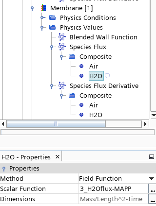
- Apply the newly created field functions for the flux and flux derivative under the Physics Values.
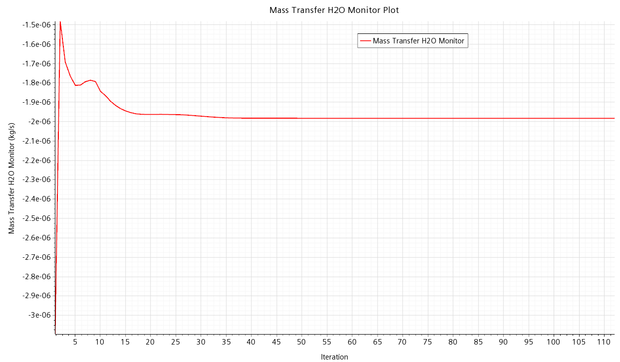
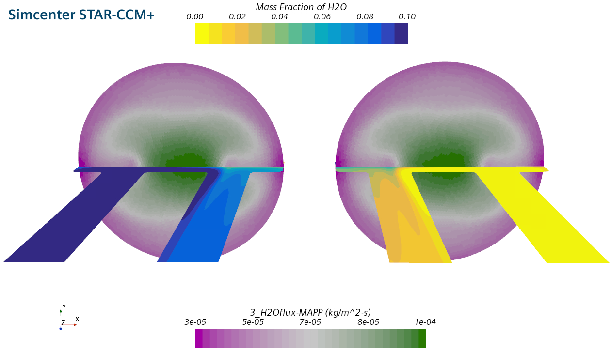
Here is another view of the membrane chamber. The membrane with the species flux is shown, the two sides are shown mirrored, left and right.
