Simcenter 3D Solutions Assembly FEM Bridge Analysis in Simcenter 3D - Part 2 - Mesh the geometry
2023-08-08T15:34:04.000-0400
Simcenter 3D
Summary
This tutorial shows how to go about setting up a structural analysis using an Assembly FEM in Simcenter 3D. The aim is to introduce the user to the power of Assembly FEMS and familiarize them with the approach and concepts involved.
Details
Part 2 - Mesh the geometry
Step 6: Create the Midsurfaces for Shell Meshing
Step 7: Stitch Midsurface Edges
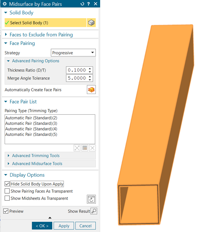
Step 6: Create the Midsurfaces for Shell Meshing
•Select the Midsurface by Face Pairs  tool in the Geometry Preparation group of the Home tab tool ribbon
•Select the section
•Click on the Automatically Create Face Pairs  button
•Ensure that the Hide Solid Body Upon Apply checkbox is checked
•Press OK
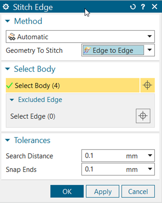
Step 7: Stitch Midsurface Edges
•Double click the Square_Section_01_fem1 part in the Simulation File View pane using the left mouse button
•Close the information window that appears
•Select the Stitch Edge tool in the Polygon Geometry group of the Home tab tool ribbon
•Ensure that Method is set to Automatic
•Set Geometry to Stitch to Edge to Edge
•Set the Search Distance and Snap Ends Tolerances to 0.1mm
•Select all bodies in the display
•Click OK
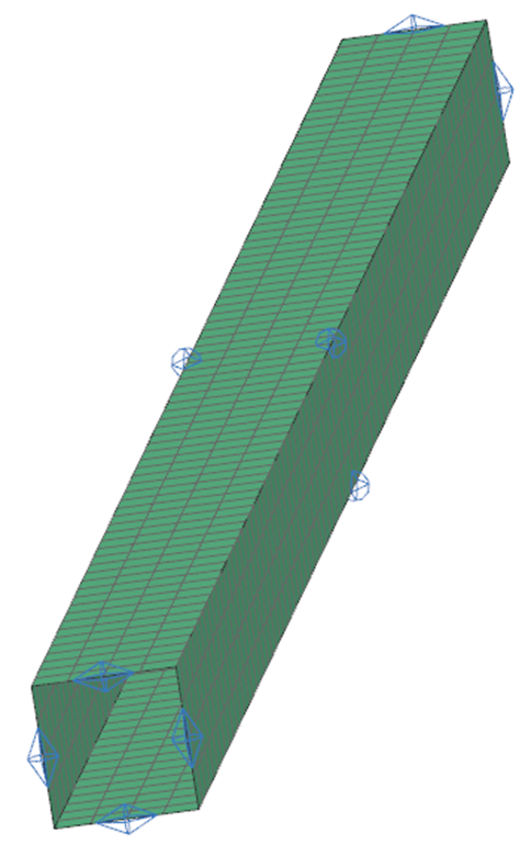
Step 8: Create the Mesh
Step 9: Assign Materials and Properties
Step 8: Create the Mesh
•Select the 2D Mapped Mesh  tool in the Mesh group of the Home tab tool ribbon
•Ensure that Type is set to CQUAD4
•Set Element Size to 50mm
•Select all bodies in the display
•Click OK
Step 9: Assign Materials and Properties
•Expand the 2D Collectors item in the Simulation Navigator
•Right-click on the ThinShell(1) item and select Edit 
•In the Mesh Collector menu that appears, click on Edit
•Click on the Choose Material button for Material 1
button for Material 1•Select Steel from the list that appears, click OK, then OK again and again
•Right-click on the 2d_mapped_mesh(1) item and select Edit Mesh Associated Data
•Set Thickness Source to Midsurface
•Click OK
This completes Assembly FEM Bridge Analysis in Simcenter 3D - Part 2 - Mesh the geometry
Please continue with Assembly FEM Bridge Analysis in Simcenter 3D - Part 3 - Assign Material and properties
This completes Assembly FEM Bridge Analysis in Simcenter 3D - Part 2 - Mesh the geometry
Please continue with Assembly FEM Bridge Analysis in Simcenter 3D - Part 3 - Assign Material and properties
Associated Components
Acoustics
Additive Manufacturing
Assembly FEM
Correlation and Updating
Durability
Electromagnetics (High Frequency)
Electromagnetics (Low Frequency)
Flexible Pipe
Laminate Composites
Margin of Safety
Motion
Multiphysics
NX Open
Nonlinear
Optimization
Pre/Post
Response Dynamics
Rotor Dynamics
Samcef Environment
Simulation Process Management
Thermal / Flow