Simcenter Testlab Neo Calibration Process
2021-08-09T14:19:16.000-0400
Summary
This article will illustrate the calibration process in Simcenter Testlab Neo.
Details
The calibration process for Simcenter Testlab (Classic) has already been covered in detail in this Knowledge Article:
Simcenter Testlab Calibration.
This article guides the user through the necessary steps to perform a calibration in Simcenter Testlab Neo.
The calibration process will be described in two examples:
- AC calibration of a microphone,
- AC calibration of an accelerometer.
AC Calibration of a microphone
Open the Acquisition Setup of Testlab Neo General Acquisition and go the Channels Task (Figure 1).
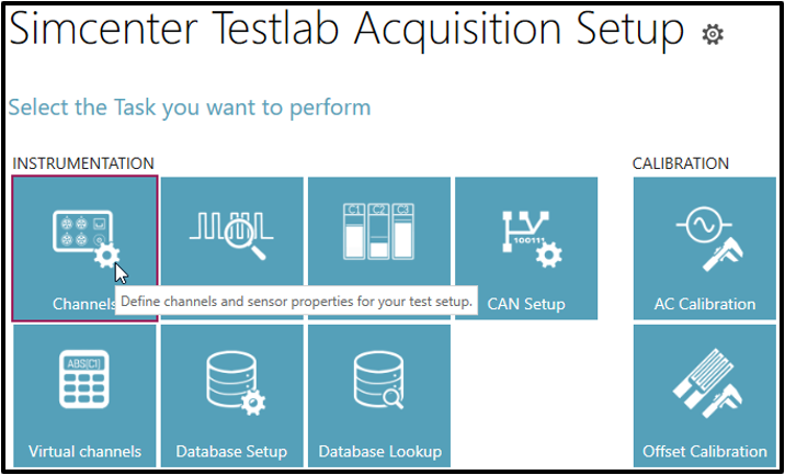 Figure 1: Task Overview - Channels
Depending on your hardware configuration, enable the channels which you have plugged into your Scadas frontend. In this case, we are measuring with a Scadas Mobile SCM02 and have plugged an ICP microphone into channel 9 and an ICP accelerometer into channel 10.
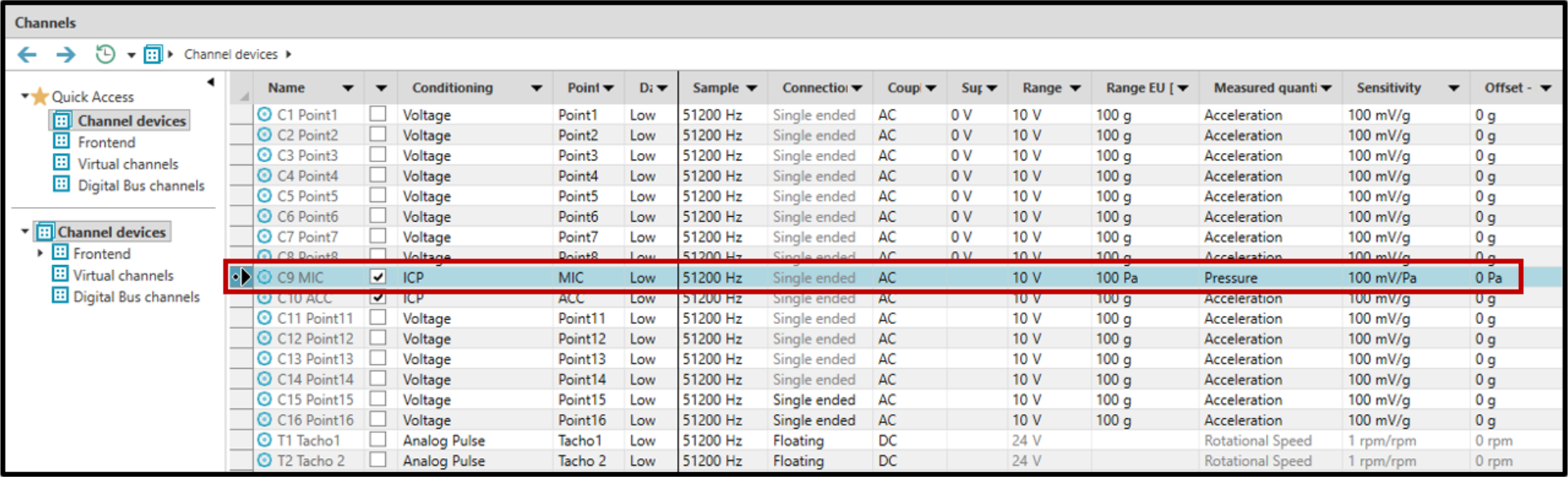 Figure 2: Channel Setup
In the Channel Setup (Figure 2), it can be seen that the conditioning input mode has been set to ICP. Set the measured quantity to Pressure so that you have the sensitivity in mV/Pa. Further properties (like Sensitivity or Range) can be left at their default values, or you may choose to change certain fields (Point ID) manually.
The next step is the calibration task (Figure 3).
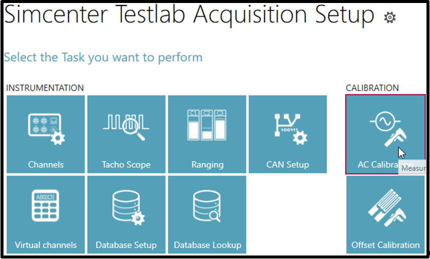 Figure 3: Task Overview – AC Calibration
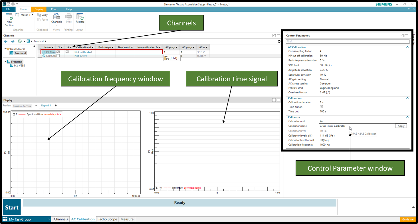 Figure 4: Overview of the Calibration window
In the blank Calibration task of Figure 4, the main parts for the calibration process are highlighted in green: The “Channels” field, the “Calibration frequency window”, “Calibration time signal” and the “Control Parameter window”.
Make sure the microphone channel which you want to calibrate is checked ON. You can only activate this if you have selected the Calibrator unit "Pa". The selection of the unit in the “Control Parameter window” must always be done first, otherwise no channel can be selected.
Select the Calibrator settings in the control parameter window (How to enter calibrator properties in Testlab Neo, will be explained in the end of this section). Insert the microphone in the calibrator and press “Start” in Testlab Neo.
If the calibrator frequency is within the specified tolerance, the calibration will start. When the calibration is finished, the newly calculated calibration values will be shown in a column called New Sensitivity. Press the Apply button to update the calibration value (Figure 5).
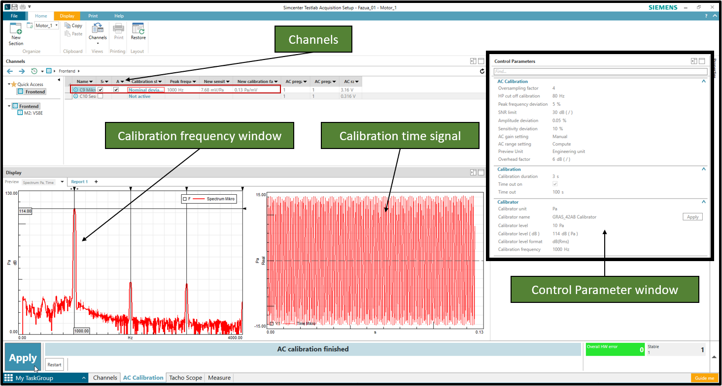 Figure 5: AC calibration of a microphone
Important to know:
The dB difference in the "Calibration frequency window" between the level of the main spectral peak and the 114dB reference level from the calibrator during the very first calibration run, depends on the initial sensitivity that is previously set in the channel setup. If the default sensitivity value 100 mV/Pa is set and the manufactured calibrated sensitivity is many times lower as in this example at approx. 7 mV/Pa, then the peak will not be expected at 114 dB. As soon as you click Apply, Testlab takes over the new sensitivity, and if you carry out the calibration again to check it, you can clearly see that the peak is at 114 dB.
How to enter calibrator properties in Testlab Neo?
Brows to the DataSources folder and open the Calibrators.csv file as highlighted in Figure 6.
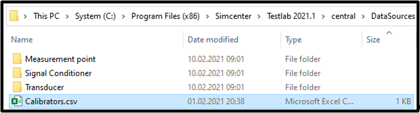 Figure 6: Path to the “Calibrators” file
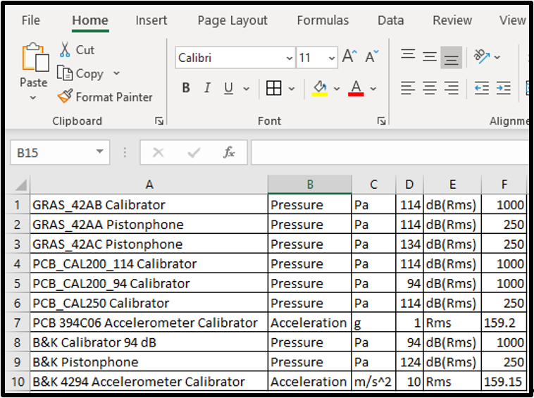 Figure 7: “Calibrators” file content
It is mandatory to keep the order of the columns as shown in Figure 7. Column A is a free field for the calibrator name, column B is the measured quantity, column C is the calibration unit, column D the calibration level, column E the calibration level (unit), and column F is the calibration frequency level.
AC Calibration of an accelerometer
The next section will illustrate the accelerometer calibration. The steps in the Channels task are the same as above for the microphone. It is not necessary to change something in the Channel setup. We can stay in the Calibration task, enable the sensor checkbox and deactivate the microphone one. Please make sure that you have changed the calibrator setting in the drop down list to your accelerometer calibrator as shown in Figure 8.
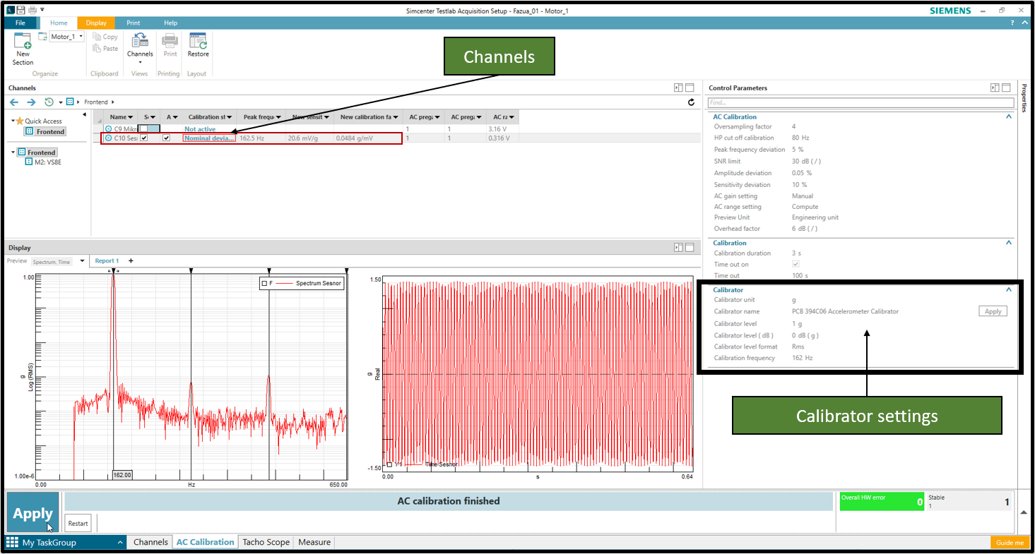 Figure 8: AC Calibration of an accelerometer
If the calibrator frequency is within the specified tolerance, the calibration starts. When the calibration is finished, the newly calculated calibration values are shown in a column called New Sensitivity. Press the Apply button for adopting the new calibration value.
If you now switch to the Channels task, you can see the new sensitivity and range values (Figure 9).
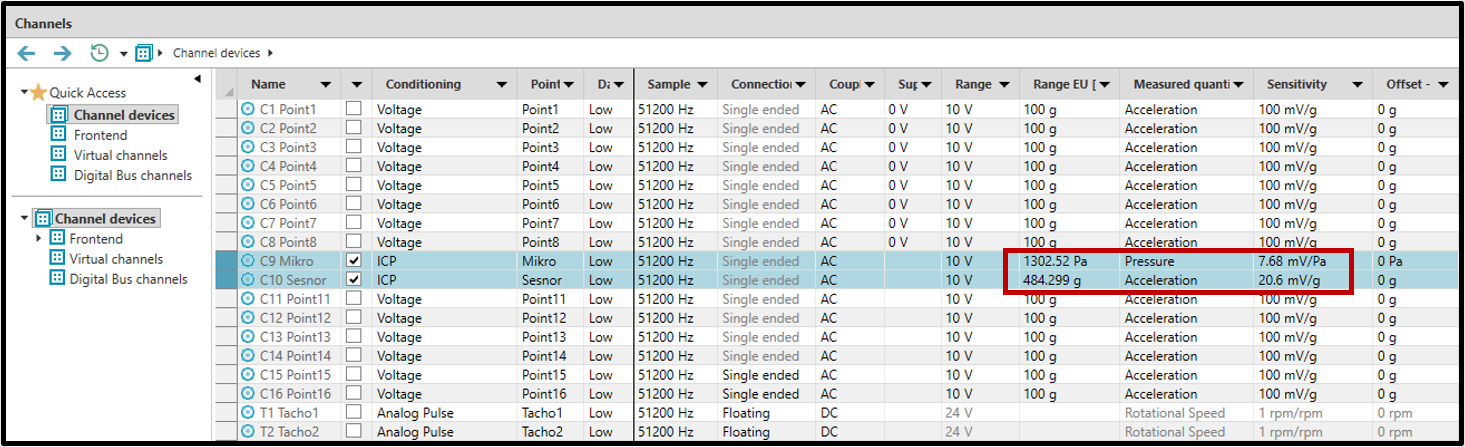 Figure 9: Channel setup with the new calibrated Sensitivity and Range values
The calibration process is finished now, and the user can continue with his application.
If you have Questions, contact your local Support Engineer or open a ticket on the Simcenter Support Portal.
Further helpful knowledge article please check the related Links:
Simcenter Testlab Calibration.
This article guides the user through the necessary steps to perform a calibration in Simcenter Testlab Neo.
The calibration process will be described in two examples:
- AC calibration of a microphone,
- AC calibration of an accelerometer.
AC Calibration of a microphone
Open the Acquisition Setup of Testlab Neo General Acquisition and go the Channels Task (Figure 1).
Figure 1: Task Overview - ChannelsDepending on your hardware configuration, enable the channels which you have plugged into your Scadas frontend. In this case, we are measuring with a Scadas Mobile SCM02 and have plugged an ICP microphone into channel 9 and an ICP accelerometer into channel 10.
Figure 2: Channel SetupIn the Channel Setup (Figure 2), it can be seen that the conditioning input mode has been set to ICP. Set the measured quantity to Pressure so that you have the sensitivity in mV/Pa. Further properties (like Sensitivity or Range) can be left at their default values, or you may choose to change certain fields (Point ID) manually.
The next step is the calibration task (Figure 3).
Figure 3: Task Overview – AC CalibrationFigure 4: Overview of the Calibration windowIn the blank Calibration task of Figure 4, the main parts for the calibration process are highlighted in green: The “Channels” field, the “Calibration frequency window”, “Calibration time signal” and the “Control Parameter window”.
Make sure the microphone channel which you want to calibrate is checked ON. You can only activate this if you have selected the Calibrator unit "Pa". The selection of the unit in the “Control Parameter window” must always be done first, otherwise no channel can be selected.
Select the Calibrator settings in the control parameter window (How to enter calibrator properties in Testlab Neo, will be explained in the end of this section). Insert the microphone in the calibrator and press “Start” in Testlab Neo.
If the calibrator frequency is within the specified tolerance, the calibration will start. When the calibration is finished, the newly calculated calibration values will be shown in a column called New Sensitivity. Press the Apply button to update the calibration value (Figure 5).
Figure 5: AC calibration of a microphoneImportant to know:
The dB difference in the "Calibration frequency window" between the level of the main spectral peak and the 114dB reference level from the calibrator during the very first calibration run, depends on the initial sensitivity that is previously set in the channel setup. If the default sensitivity value 100 mV/Pa is set and the manufactured calibrated sensitivity is many times lower as in this example at approx. 7 mV/Pa, then the peak will not be expected at 114 dB. As soon as you click Apply, Testlab takes over the new sensitivity, and if you carry out the calibration again to check it, you can clearly see that the peak is at 114 dB.
How to enter calibrator properties in Testlab Neo?
Brows to the DataSources folder and open the Calibrators.csv file as highlighted in Figure 6.
Figure 6: Path to the “Calibrators” fileFigure 7: “Calibrators” file contentIt is mandatory to keep the order of the columns as shown in Figure 7. Column A is a free field for the calibrator name, column B is the measured quantity, column C is the calibration unit, column D the calibration level, column E the calibration level (unit), and column F is the calibration frequency level.
AC Calibration of an accelerometer
The next section will illustrate the accelerometer calibration. The steps in the Channels task are the same as above for the microphone. It is not necessary to change something in the Channel setup. We can stay in the Calibration task, enable the sensor checkbox and deactivate the microphone one. Please make sure that you have changed the calibrator setting in the drop down list to your accelerometer calibrator as shown in Figure 8.
Figure 8: AC Calibration of an accelerometerIf the calibrator frequency is within the specified tolerance, the calibration starts. When the calibration is finished, the newly calculated calibration values are shown in a column called New Sensitivity. Press the Apply button for adopting the new calibration value.
If you now switch to the Channels task, you can see the new sensitivity and range values (Figure 9).
Figure 9: Channel setup with the new calibrated Sensitivity and Range valuesThe calibration process is finished now, and the user can continue with his application.
If you have Questions, contact your local Support Engineer or open a ticket on the Simcenter Support Portal.
Further helpful knowledge article please check the related Links:
- Simcenter Testlab Overview
- Simcenter Testlab Neo Displays
- Simcenter Testlab Neo Ribbon Tips
- Simcenter Testlab Neo: Pivot Table
- Simcenter Testlab Neo Process Designer
- Simcenter Testlab Neo Audio Replay
- Importing Video in Simcenter Testlab Neo
- Using Multiple Segments with Simcenter Testlab Neo
- Simcenter Testlab Active Picture
- Simcenter Testlab: Templates
- Simcenter Testlab: Batch Reporting
- Simcenter Testlab: Display Layouts
- Simcenter Testlab: Customized Legend Text
- Simcenter Testlab: Curve Linestyles
- Simcenter Testlab: Cursor Tips and Tricks
- Simcenter Testlab: Coupled Cursors and Coupled Limits
- Simcenter Testlab: Interactive order cursor!
- Simcenter Testlab: Report Creation for each individual ModeSet
- Simcenter Testlab Calibration